Description
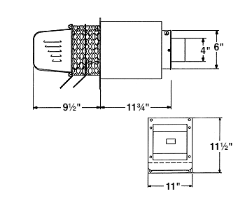
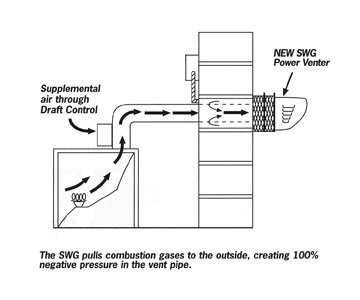
The SWG combines the motor, blower, and vent hood in one complete, easy to install unit. The SWG mounts on the outside of the building and pulls the combustion gas from the appliance through the outside wall utilizing 100% negative pressure.
Benefits of the SWG Power Venter include:
- 100% Negative pressure in the vent pipe for maximum safety.
- No need to seal vent pipe joints, saving time and money.
- Significantly longer vent lengths than positive pressure, direct vent systems.
- The SWG is recommended by major heating appliance manufacturers.
Leisure Line Stoves generate heat through combustion of fuel. The heat is transferred through the heat exchanger and distributed to the conditioned room. The products of combustion, however, must be vented safely out of the structure. In a conventional chimney, venting is achieved by the natural lifting action of the hot combustion gas. New, efficient systems absorb more of the heat in the heat exchanger and produce lower temperature vent gas. Lower temperature gas does not rise as quickly or as reliably as in older, less efficient systems. A power venter uses a motorized blower to vent the products of combustion. A power venter is interlocked with the appliance to ensure that proper draft is achieved.
Planning the Venting System
Location of the termination of the venting system should comply with the National Fuel Gas Code, A.N.S.I. Z223.1, manufacturer’s recommendations and/or applicable local codes. See Diagram for typical terminal locations.

- The exit termination of a mechanical draft system must not be less than 7′ above grade when located adjacent to a public walkway.
- The vent termination of a direct vent or sealed combustion appliance with an input of 50,000 BTU’s per hour or less must be located at least 9″ from any opening through which vented gases could enter the building. With an input over 50,000 BTU’s per hour, a 1′ termination clearance is required. Another term for direct
vent is sealed combustion. - The venting systems with the exception of direct vent appliances, must terminate at least 4′ below, 4′ horizontally, or 1′ above any door, window or gravity air inlet into the building.
- The bottom of the vent terminal must be located at least 1′ above finished grade.
- A venting system must terminate at least 3′ above any forced air inlet located within 10′.
- The vent termination point must not be installed closer than 3′ from an inside corner of an L-shaped structure.
- The vent termination should not be mounted directly above or within 3′ horizontally from an oil tank vent or gas meter. (not shown)
Clearance to Combustible Material
If mounting the venting system near combustible materials, refer to Diagram A for allowable installation clearances. Clearances are based on an installation using single wall steel vent pipe. If manufactured double wall vent pipe is required or used for the installation, clearance should be based on the vent pipe’s rated clearance. Always check local code requirements for code restrictions.
Routing of the vent system and clearances for the vent pipe may be planned once the termination location is determined. Route the vent pipe from the stove to the venter using as few elbows as possible. The horizontal section of the vent pipe should have a slight upward slope from the stove to the venter. The vent pipe size (diameter) can be smaller than a typical chimney vented system and still overcome the higher pressure losses because the power venter mechanically creates the required draft or airflow to vent the system.
Diagram A
Single Pipe System
| Allowable Inlet Temperature | Clearance (B) |
| 400°F or less | 12″ min. |
| 550°F or less | 12″ min. |
Insulated Double Pipe System
| Allowable Inlet Temperature | Clearance (B) |
| 400°F or less | 2.5″ min. |
| 550°F or less | 2.5″ min. |


Extension Kits
The standard SWG Power Venter is designed for walls up to 8″ thick. PEK extension kits allow the SWG to be installed into walls up to 16″ thick. The PEK kit includes the inner/outer pipe extension and air flow damper.

| Power Venter Model | Extension Kit Model |
| SWG – 4HD | PEK – 4 |